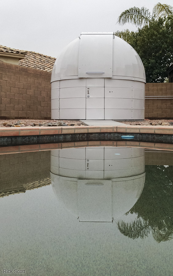
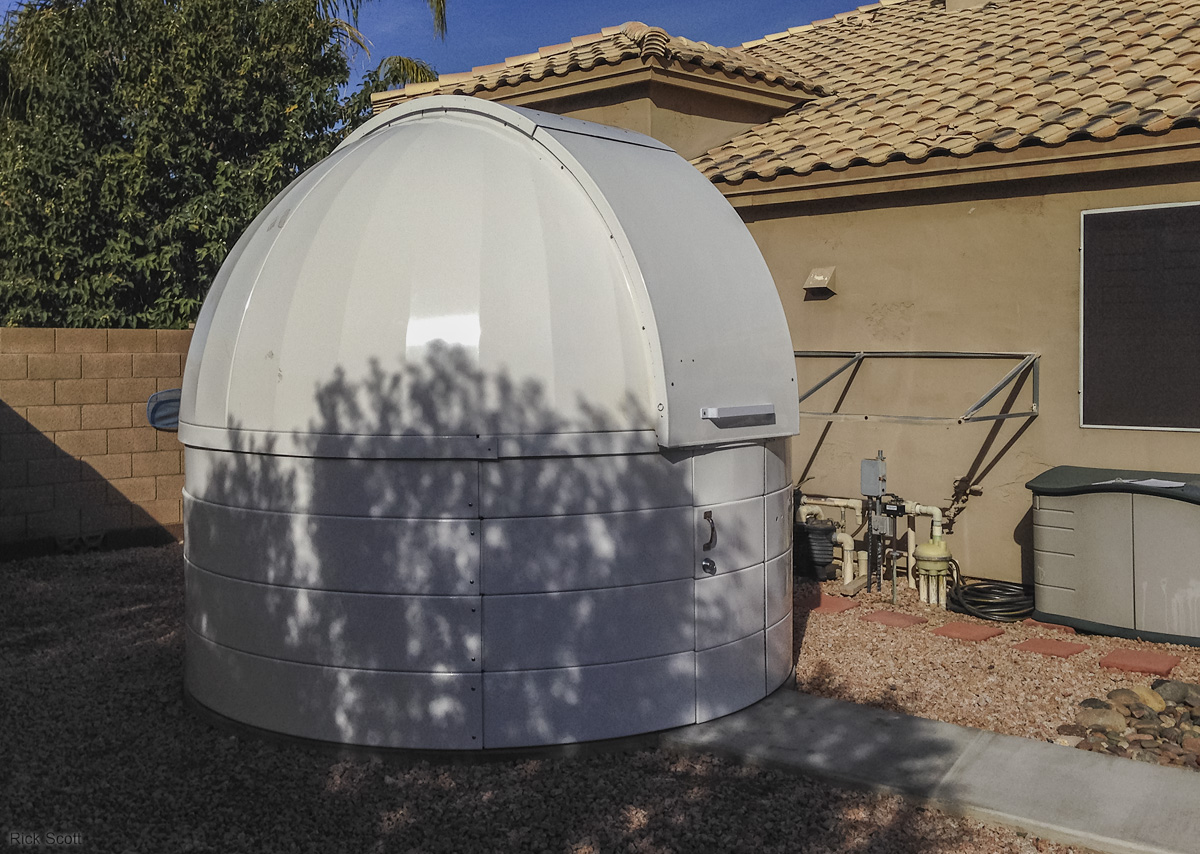
The completed JaZ 2 Observatory reflecting off my pool. (1/16/2016)
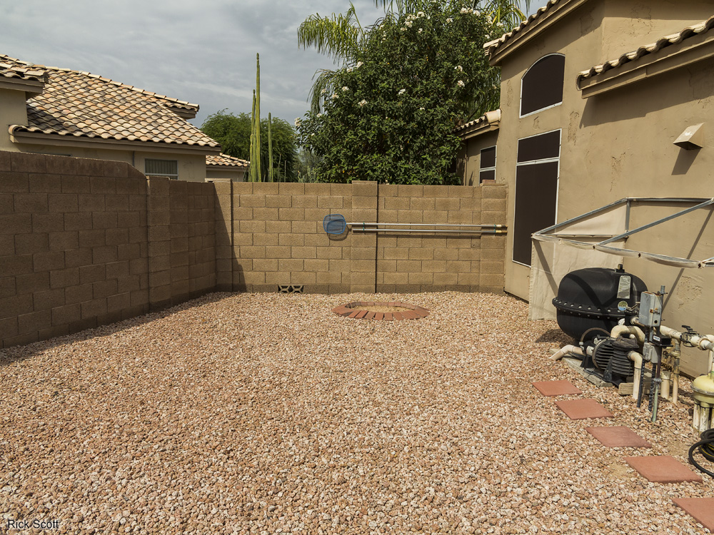
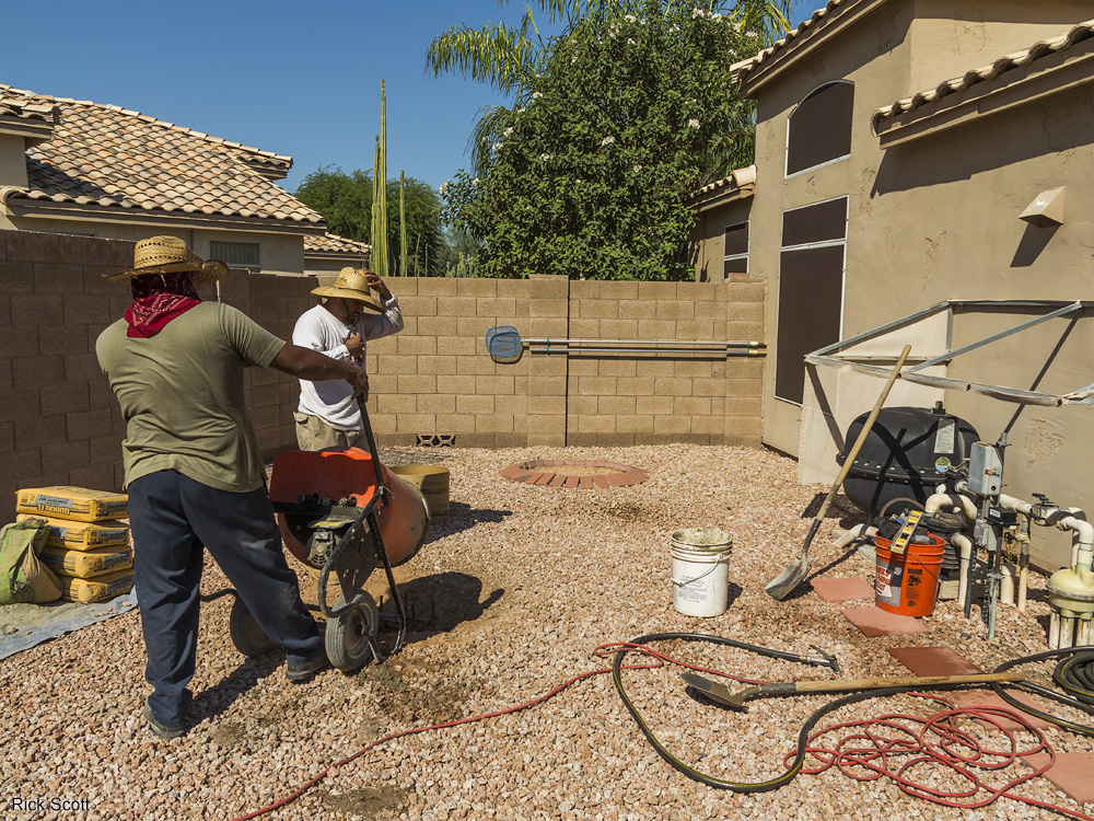
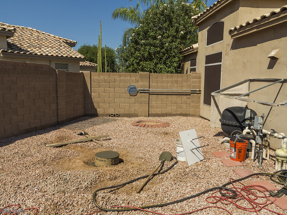
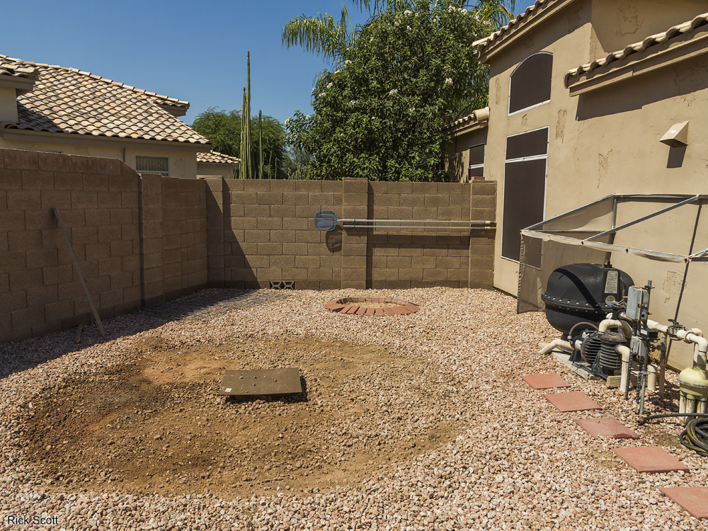
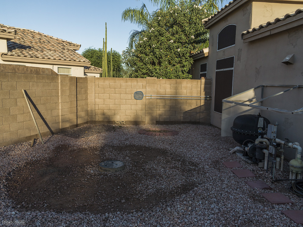
The side yard where the observatory will be located. (9/13/2015)
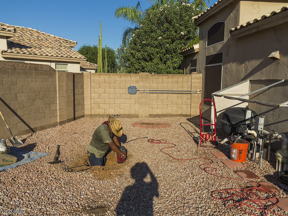
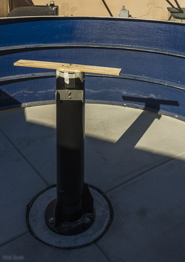
Digging the hole for the pier foundation. (9/14/2015)
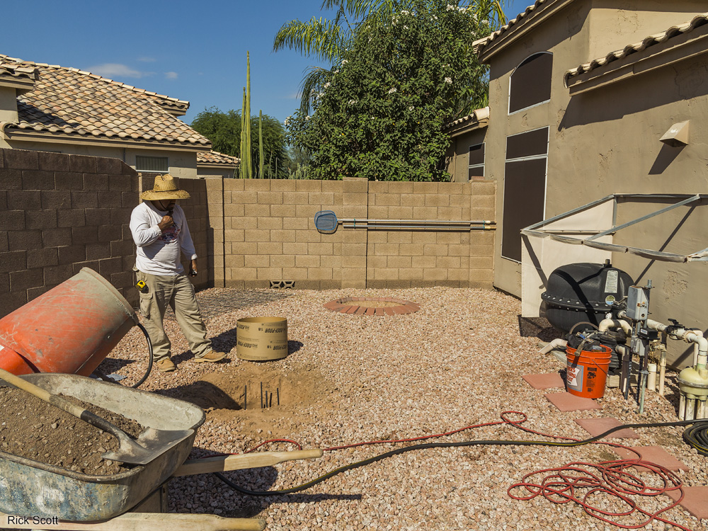
Inspecting the rebar for the pier foundation. The base of the foundation is 3 feet in diameter. (9/14/2015)
Pouring concrete into the lower part of the pier foundation. (9/14/2015)
The upper part of the pier foundation uses a 12 inch tube to define its diameter. (9/14/2015)
Three anchor bolts with coupling nuts are sunk into the concrete and held in place with a wooden jig. (9/14/2015)
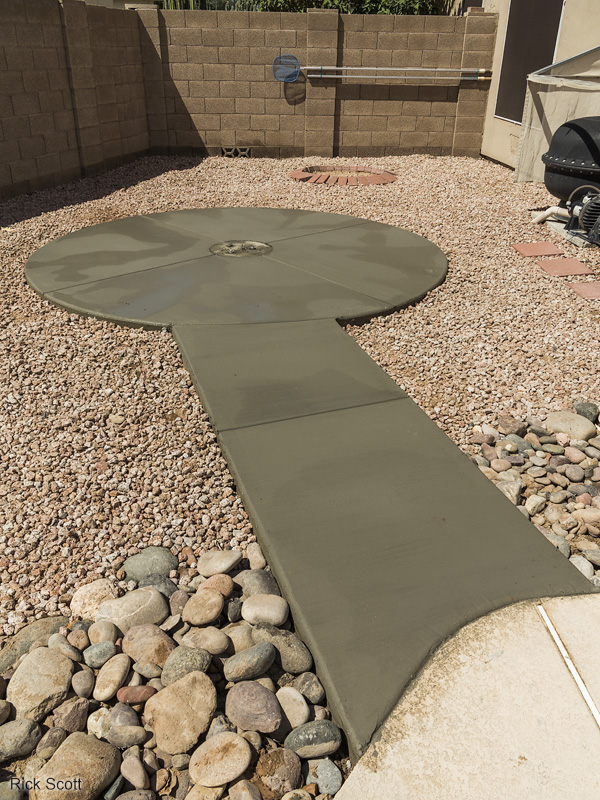
The pier foundation with the anchor bolt jig removed. The gravel is being cleared away for the 10 foot diameter concrete observatory floor. (9/15/2015)
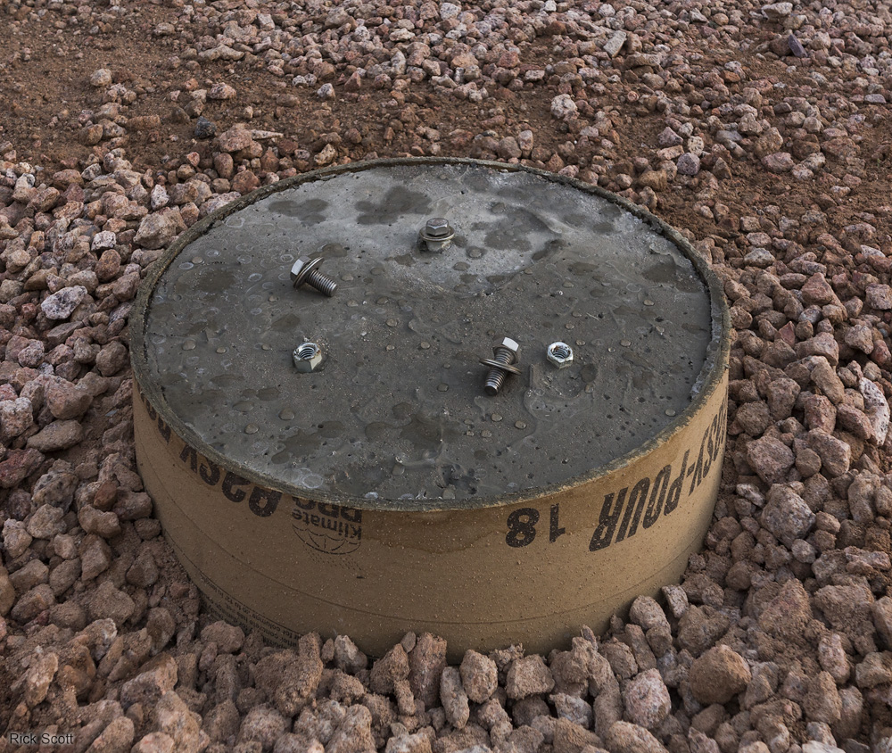
The anchor bolts with coupling nuts to attach the telescope mounting pier. (9/15/2015)
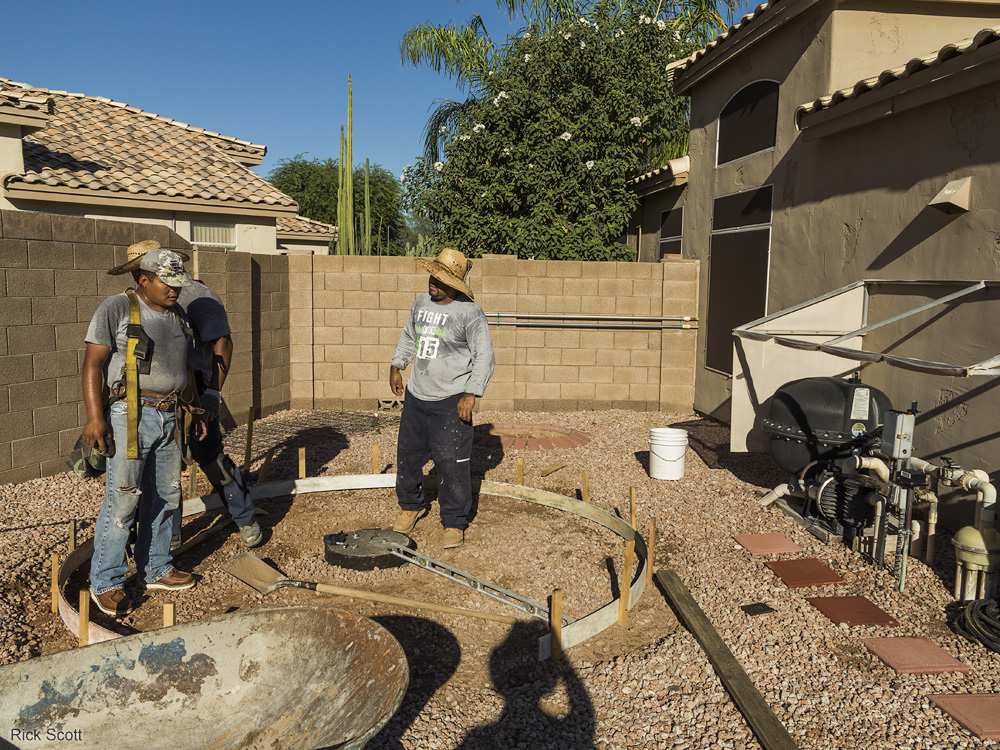
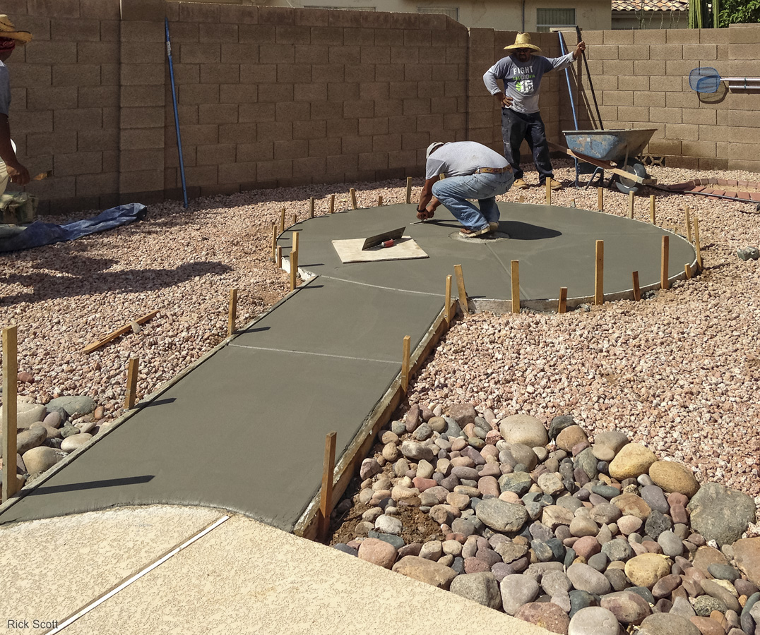
Building the form for the observatory floor. After the cardboard tube is removed, the pier
foundation
was wrapped with a felt spacer to provide some vibration isolation from the floor. (9/15/2015)
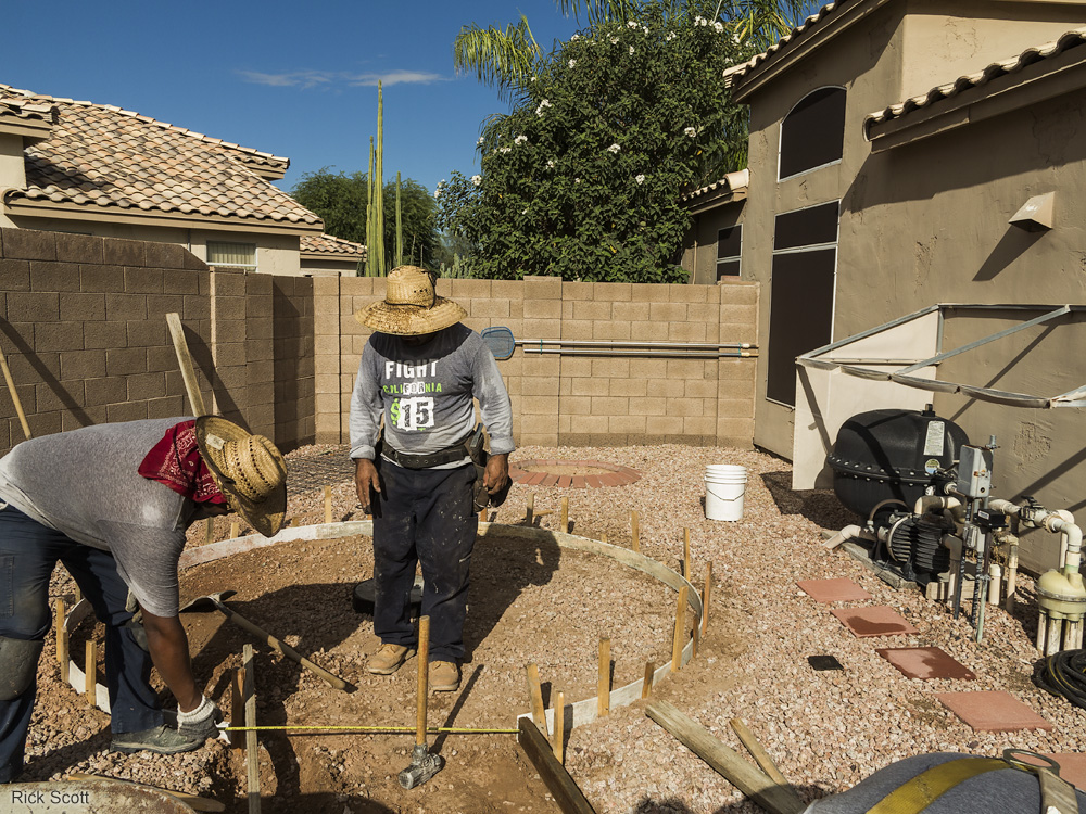
Building the form for the entrance walkway. (9/15/2015)
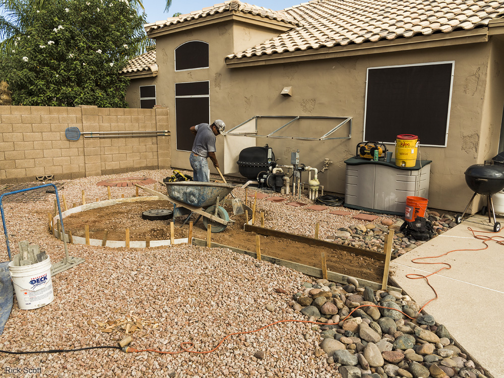
Prepping the ground for the rest of the concrete. (9/15/2015)
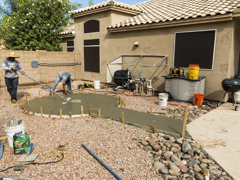
Smoothing the freshly poured concrete. (9/15/2015)
Touching up the concrete surface. (9/15/2015)
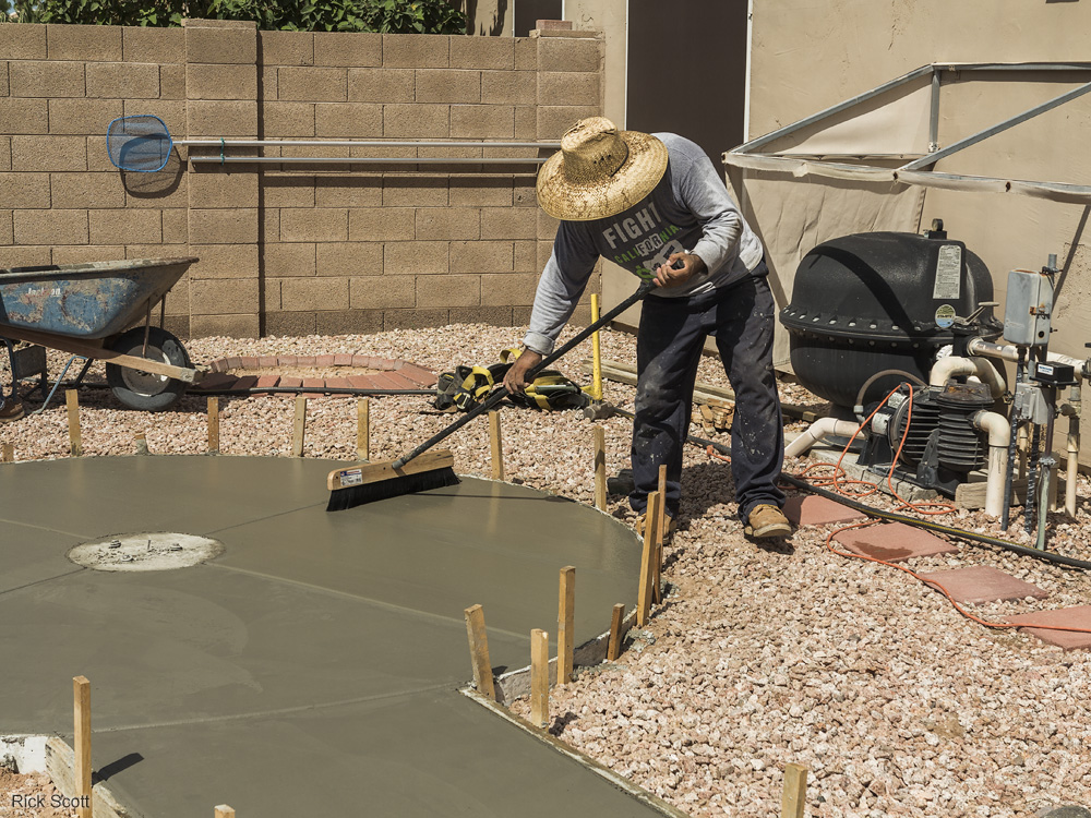
Brushing the concrete to create a texture so it's not slippery when wet. (9/15/2015)
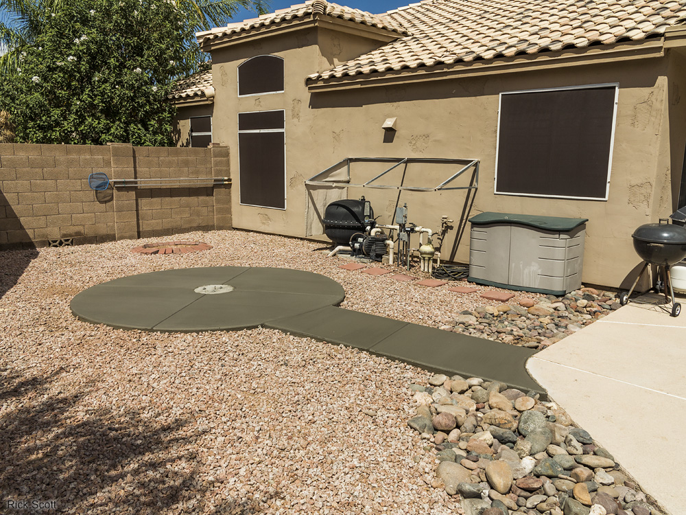
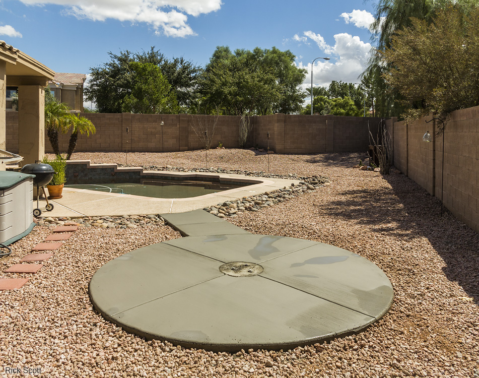
The concrete floor, walkway and pier foundation curing without the forms. This was
completed
two months before the dome was delivered to give it sufficient time to dry. (9/15/2015)
The concrete floor, walkway and pier foundation curing without the forms. (9/15/2015)
The concrete floor, walkway and pier foundation curing without the forms. (9/15/2015)
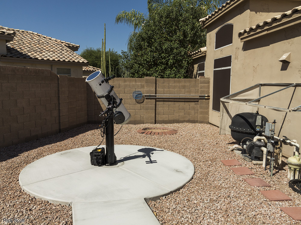
I did some solar observing to test the observatory site. I figured I might as well use it since it was there. (9/25/2015)
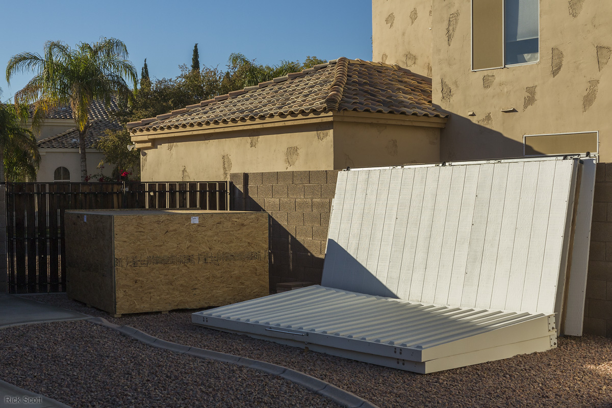
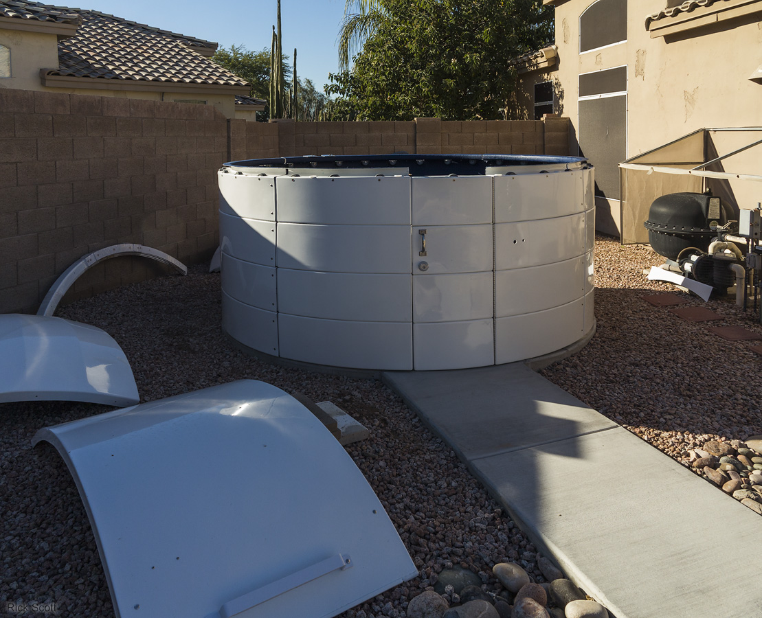
The day the dome was delivered (the large brown shipping crate). To its right are parts for my previous roll-off roof observatory. (11/20/2015)
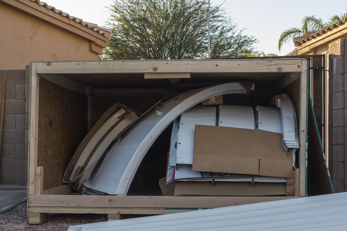
First peek inside the shipping crate for the dome. (11/20/2015)
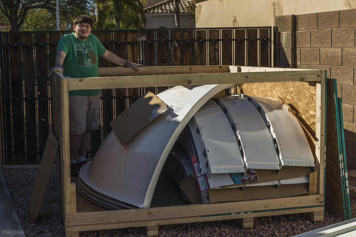
My son, Jacob (the J in JaZ), helping me unpack the observatory dome. (11/22/2015)
There's a whole lot of parts to assemble to make the observatory. (11/22/2015)
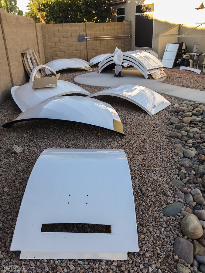
Jacob and I stacked up some of the wall panels to get a feel for what it will be like. (11/22/2015)
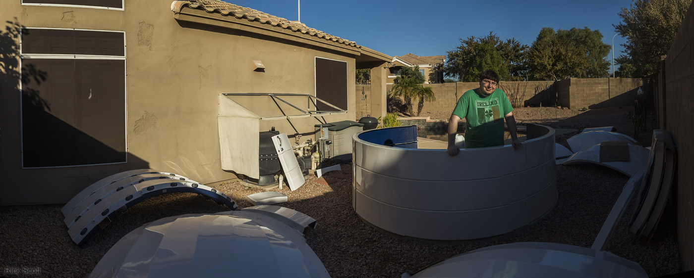
Jacob and I stacked up some of the wall panels to get a feel for what it will be like. (11/22/2015)
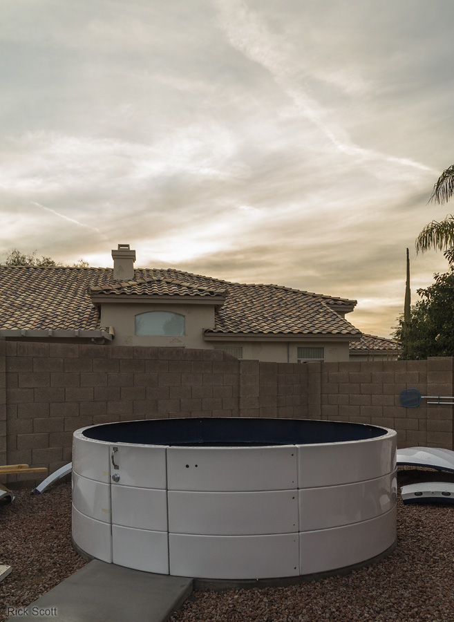
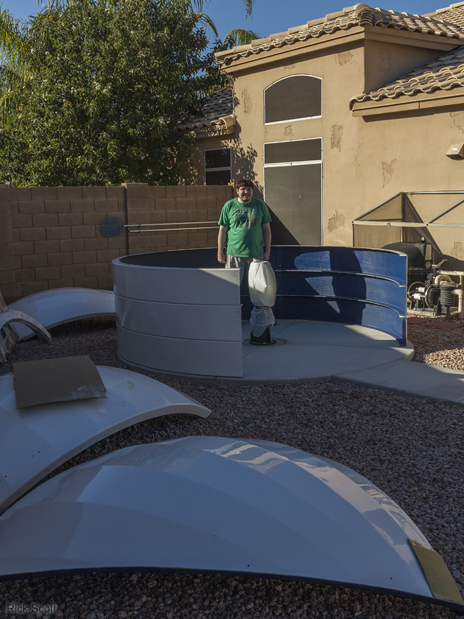
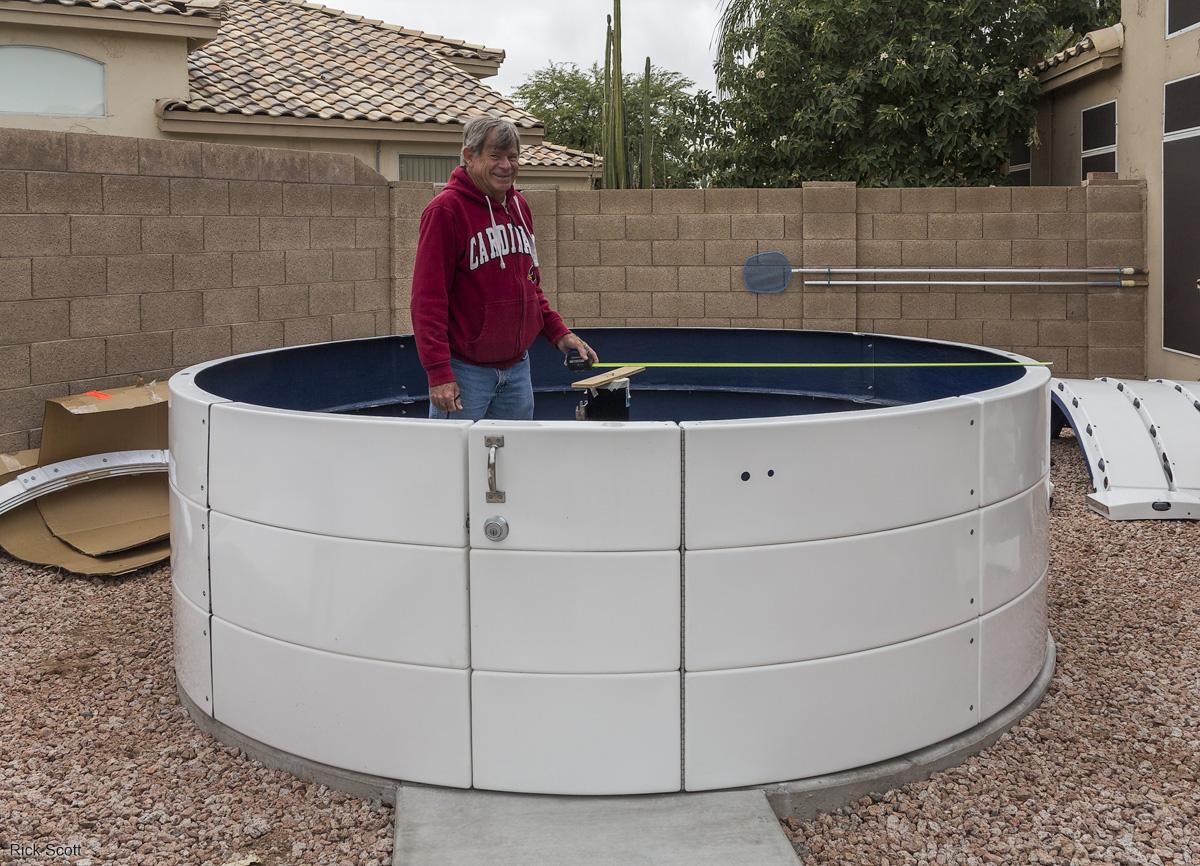
The first three wall and door layers bolted together prior to leveling and making round. (12/4/2015)
The alignment jig Bob and I built for leveling and rounding the observatory walls. (12/5/2015)
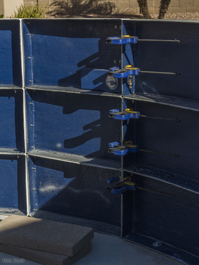
The door clamped shut for the leveling and rounding operation that was a lot more work than we anticipated. (12/5/2015)
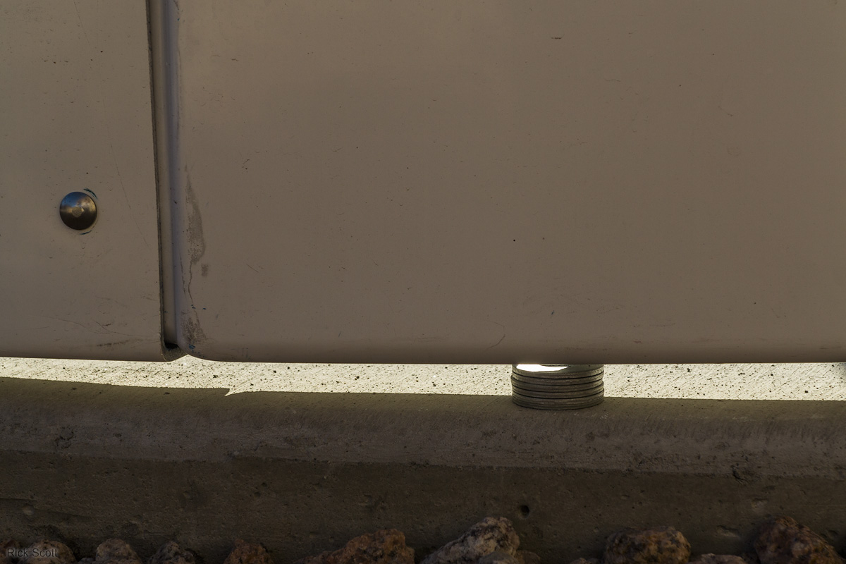
I used large fender washers for the leveling shims. Some places required no shims and others like this one required a large stack. When the observatory was finished, I filled the gap with expanding foam and then overcoated that with silicone. (12/5/2015)
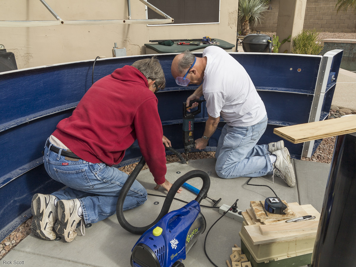
Bob and I drilling holes in the concrete for anchor nuts to bolt down the observatory. (12/12/2015)
Bob demonstrating one of the methods we used to measured the roundness. (12/12/2015)
With the base rings (top wall section) added. The base ring has the rollers that the dome rotates on. (12/18/2015)
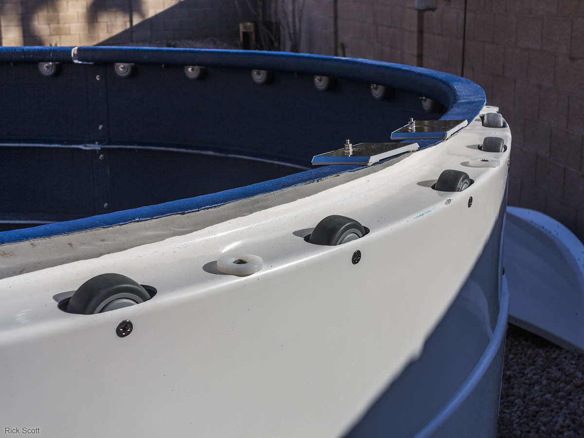
Base ring details showing the vertical and lateral rollers, reverse flange, and the electrical contact pads for the shutter electric drive. The reverse flange is part of the weather protection system. (12/18/2015)
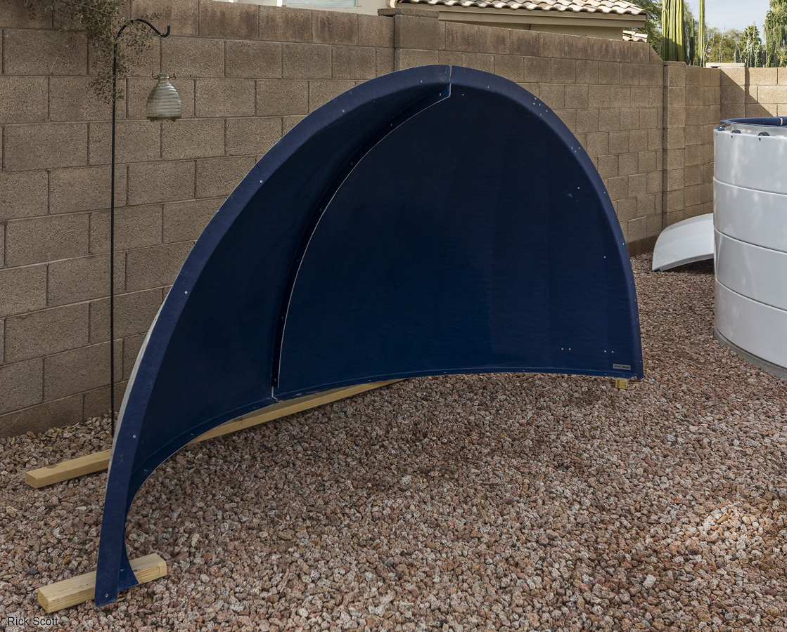
The two quadrants of the left dome half bolted together. (1/15/2016)
The two quadrants of the left dome half bolted together. (1/15/2016)
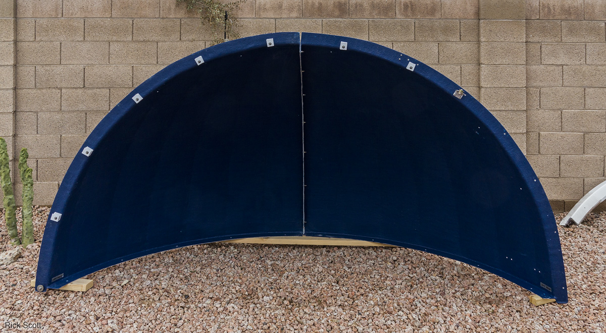
Both dome halves assembled. (1/15/2016)
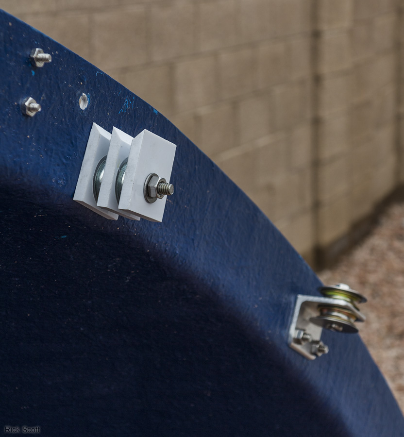
Pulleys for the electric shutter drive. (1/15/2016)
With the dome support ring (DSR) installed. This is the ring the dome attaches to that rides on the rollers. It also provide weather protection along with the reverse flange that is part of the base ring. (1/15/2016)
Close-up of the the dome support ring showing the swingout section that allows the upper part of the door to open. The dome can be rotated to any position and then the swingout section opened to provide access to inspect and clean the rollers. It must be closed to rotate the dome. (1/15/2016)
The left dome half attached to the dome support ring. (1/15/2016)
The left dome half attached to the dome support ring. (1/15/2016)
Both dome halves attached to the dome support ring without the rear cover. (1/15/2016)
Both dome halves attached to the dome support ring without the rear cover. (1/15/2016)
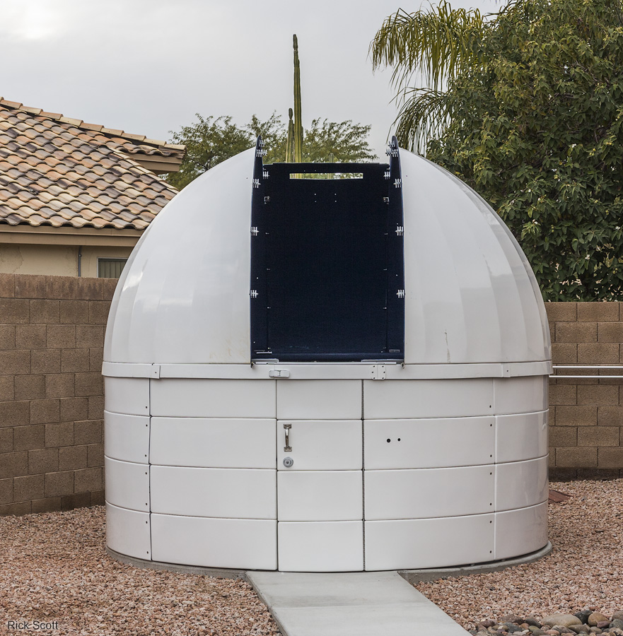
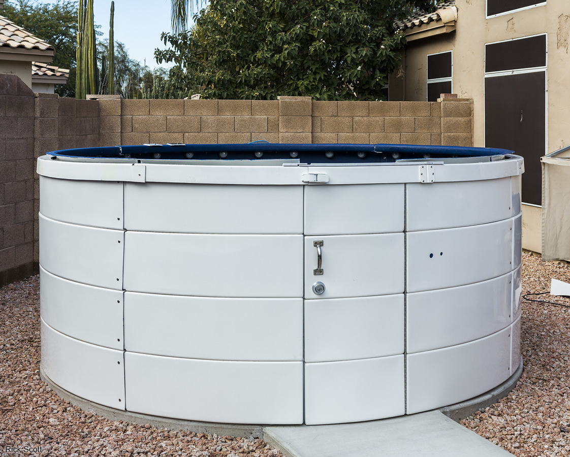
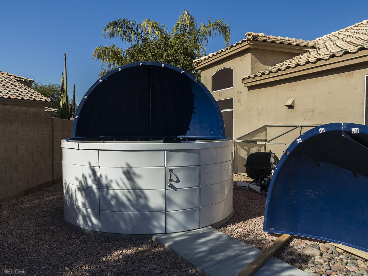
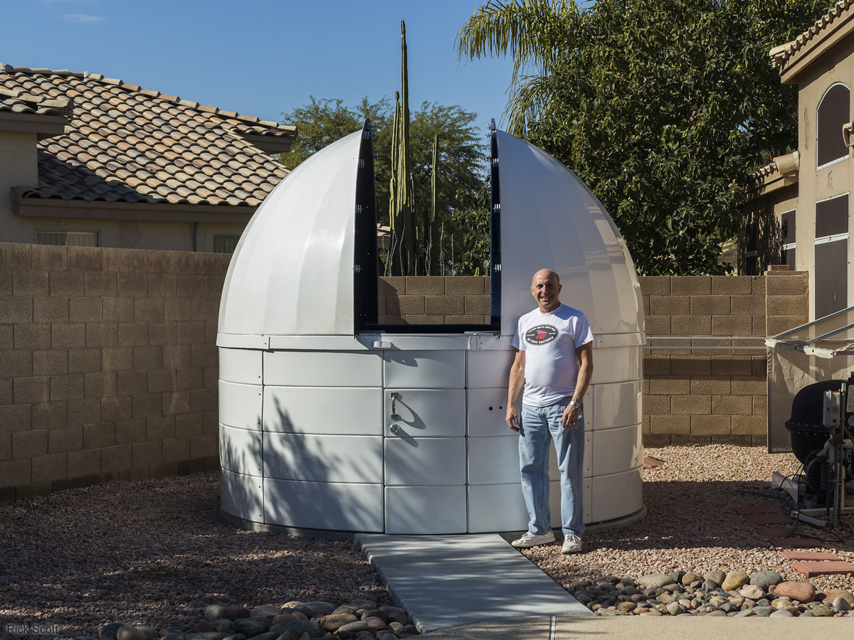
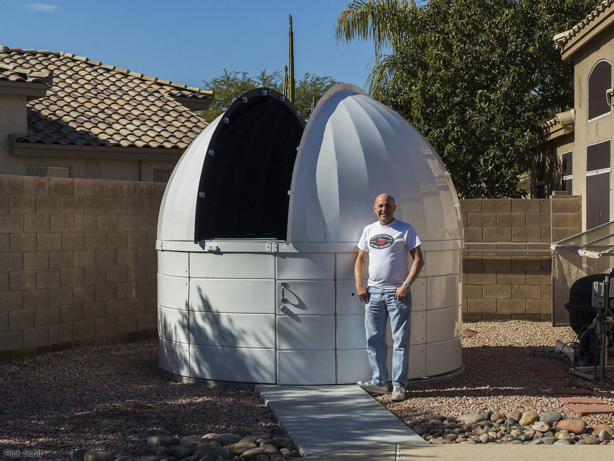
The dome with the rear cover installed. Technical Innovations setup the door such that the lower three panels make up a lower door that can be opened with the dome in any position and the upper door when the dome is in the home position. I have found this to be very useful and use this quite often. I always keep the lower door open when I use the observatory for enhanced ventilation. (1/15/2016)
First view through the dome slot. (1/15/2016)
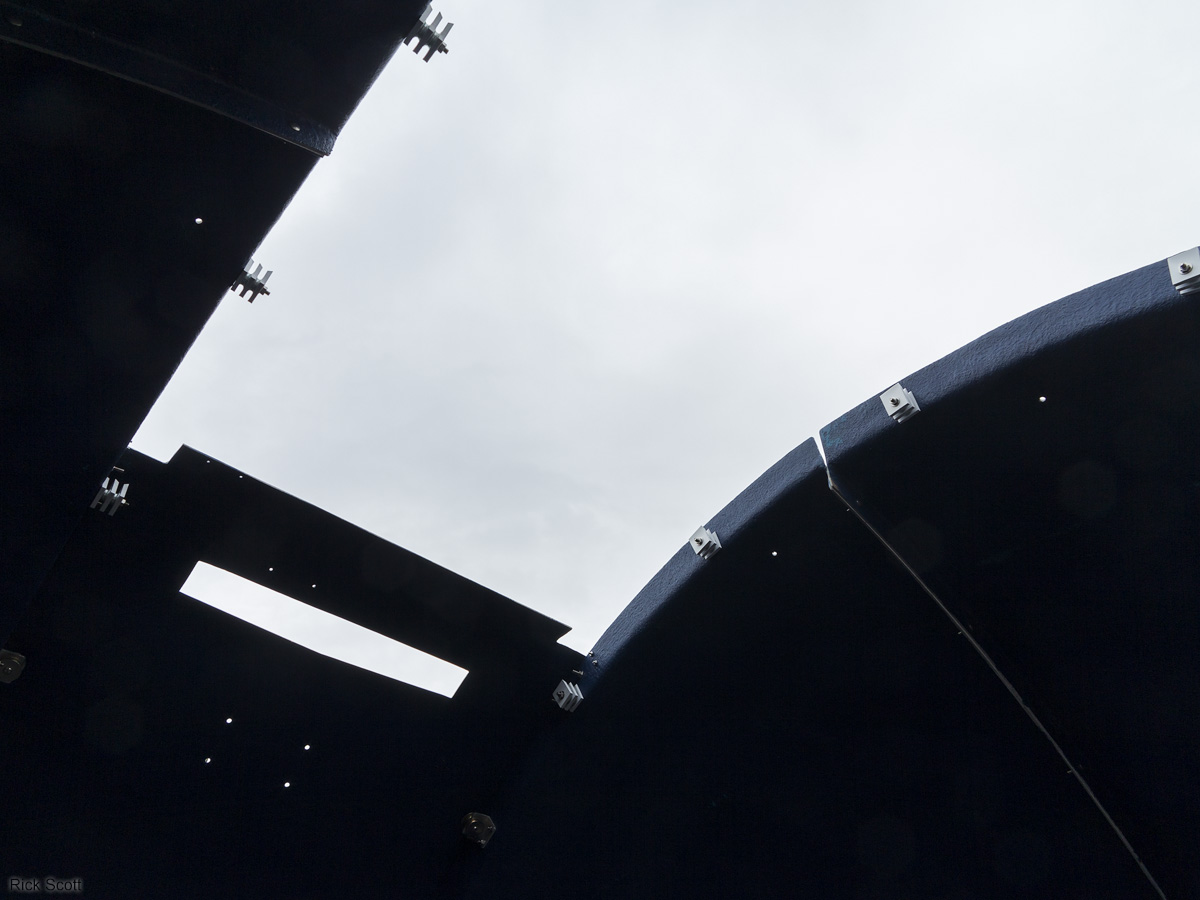
Looking up through the dome slot prior to installing the shutters. (1/15/2016)
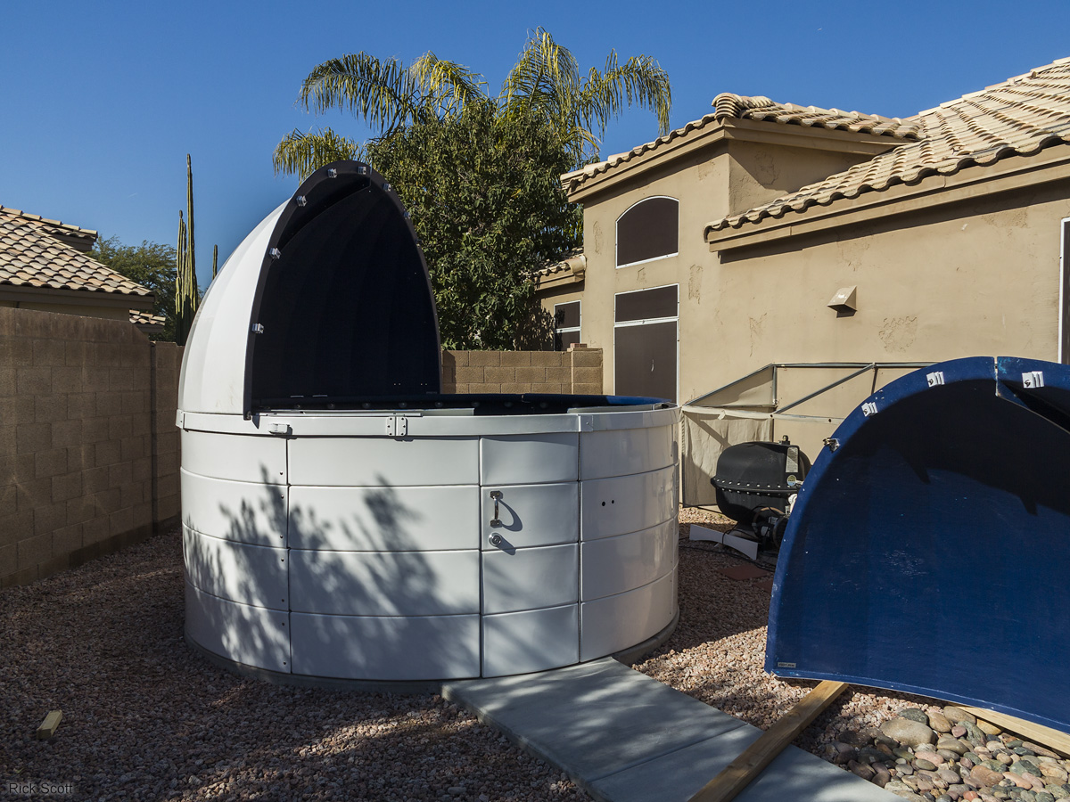
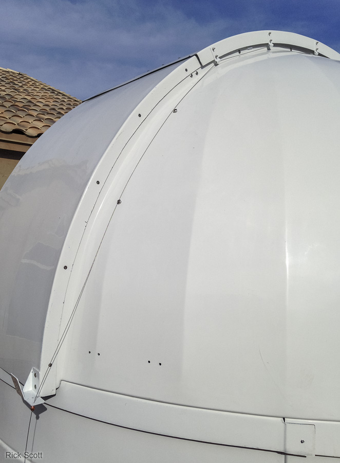
The front and top shutters installed prior to installing the safety cables. (1/16/2016)
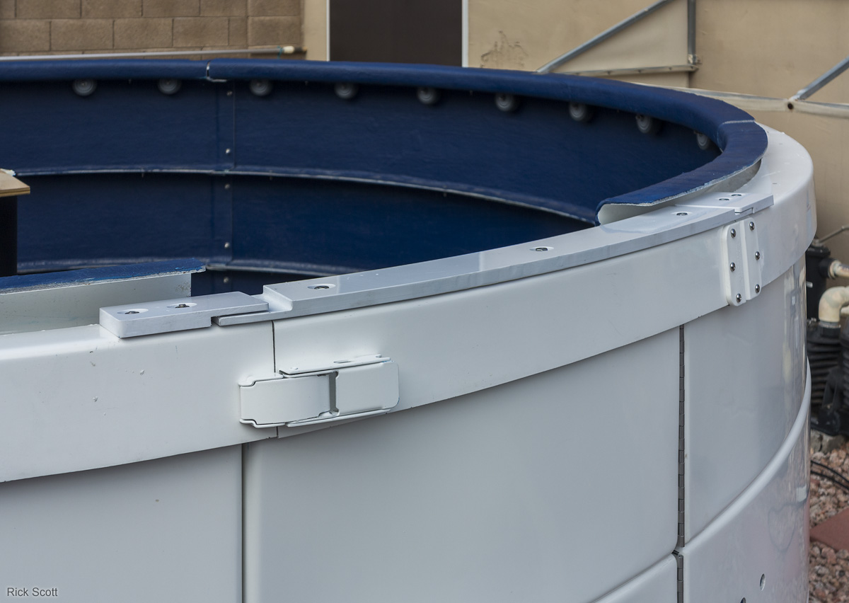
The backside of the observatory showing the rear cover, shutter catchers, and safety cables. The shutter catchers stop the shutters at the end of their travel if they're not connected to the electric shutter drive. The safety cables help prevent the shutters from blowing off in a strong wind if they are not all the way in the closed position and secured with the safety pins. (1/16/2016)
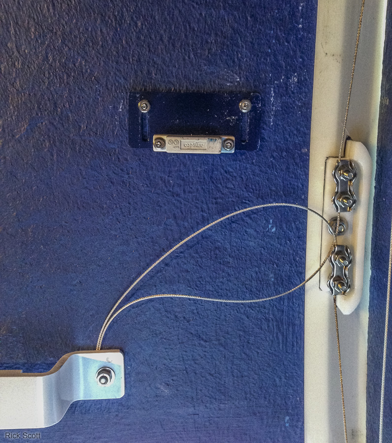
The rear showing how the cables run through the j-guides on the top shutter and connect to the shutter catchers. Cable guide posts on the dome keep the cables from sliding down it. (1/16/2016)
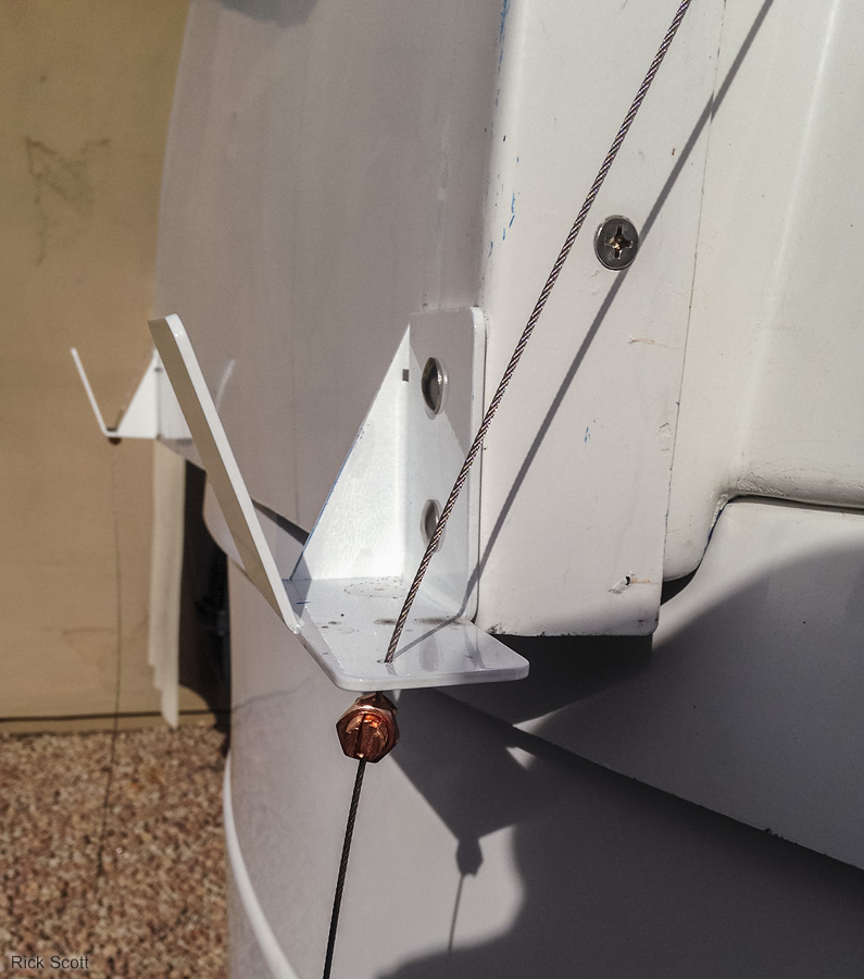
Copper cable clamps are used to secure the ends of the cables and provide the method used to adjust the cable tension. (1/16/2016)
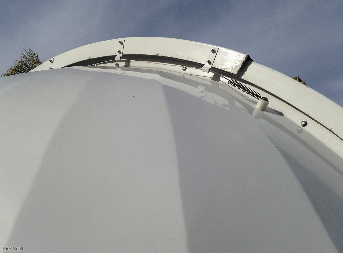
The left cable running through the j-guides on the top shutter and connected to the spring tensioner. (1/16/2016)
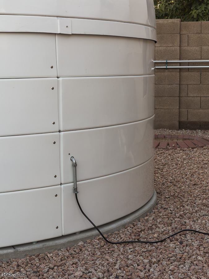
I used conduit parts to bring the electrical power into the wall of the observatory. The cord coming out of it is a heavy-duty outdoor-rated appliance cable that is plugged into an outlet associated with my pool pump/filter. This allows for a quick disconnect if necessary. (1/20/2016)
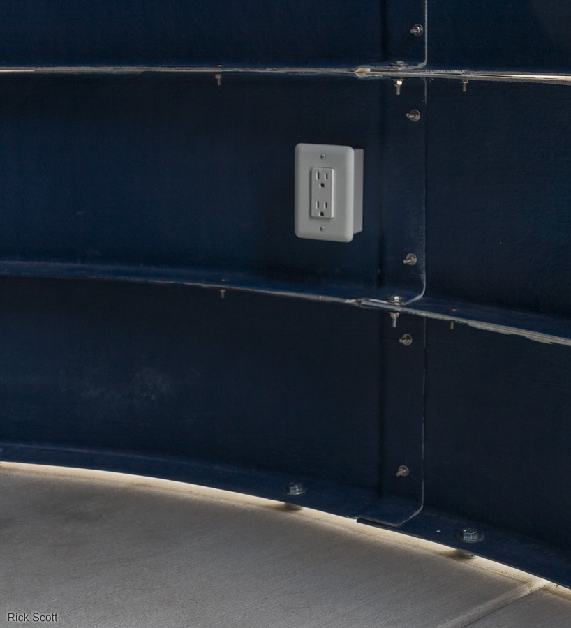
The electrical power from the conduit feeds directly into the back of this outlet box. I later added two more outlets space evenly around the observatory using each electrical box as the junction box to wire the next one in the chain. (1/20/2016)
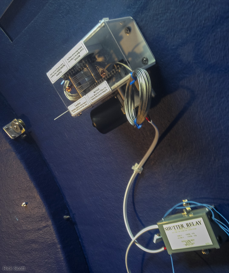
This winch drives the cables that opens and closes the shutters. It is controlled by a switch on the power supply through the relay box. The relay box senses the position of two magnetic limit switches so it knows when to stop the shutters. (1/28/2016)
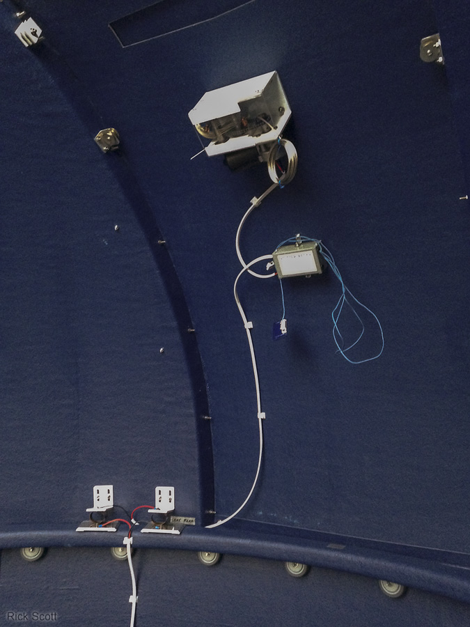
A wider view that includes the contact pads that connect the electric shutter drive to the power supply when the dome is in the home position. (1/28/2016)
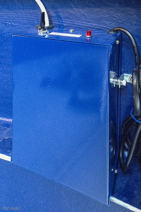
The power supply box for the electric shutter drive. It can also power an optional dome rotation system that I didn't purchase. The shutter control switch pokes through a hole in the observatory wall so it can be controlled from the outside. The switch on top of the power supply is to control dome rotation. (1/28/2016)
The cables from the winch are attached to shuttles on each side of the front shutter. I secured the cable ends by clamping them under the inner shutter handle. The magnet shown here controls the open position magnetic limit switch. (1/29/2016)
The electric shutter drive system. The shutters are in the fully opened position that is determined by the upper magnetic limit switch shown in this photograph. The other limit switch is for the fully closed position. (1/29/2016)
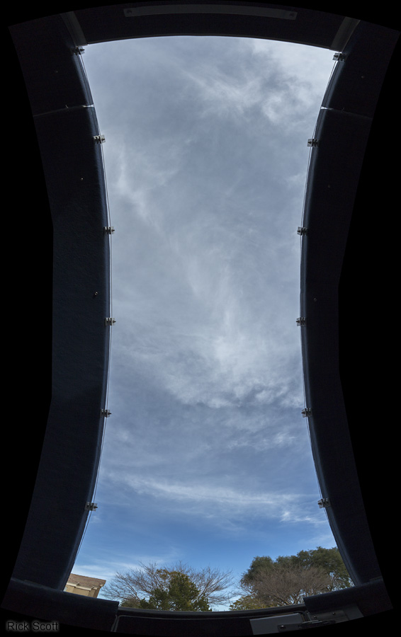
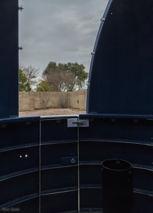
Vertical panorama looking out of the dome slot. (2/14/2016)
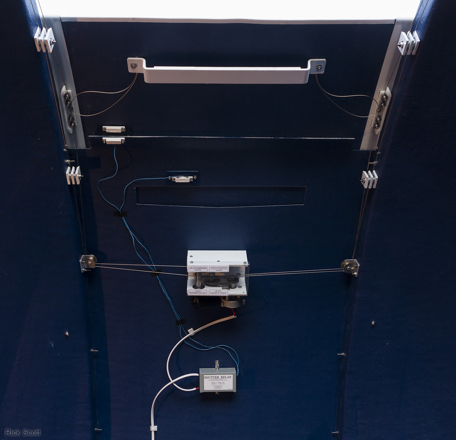
360 degree panorama of the observatory interior showing the routing of the power and control cables. (2/14/2016)
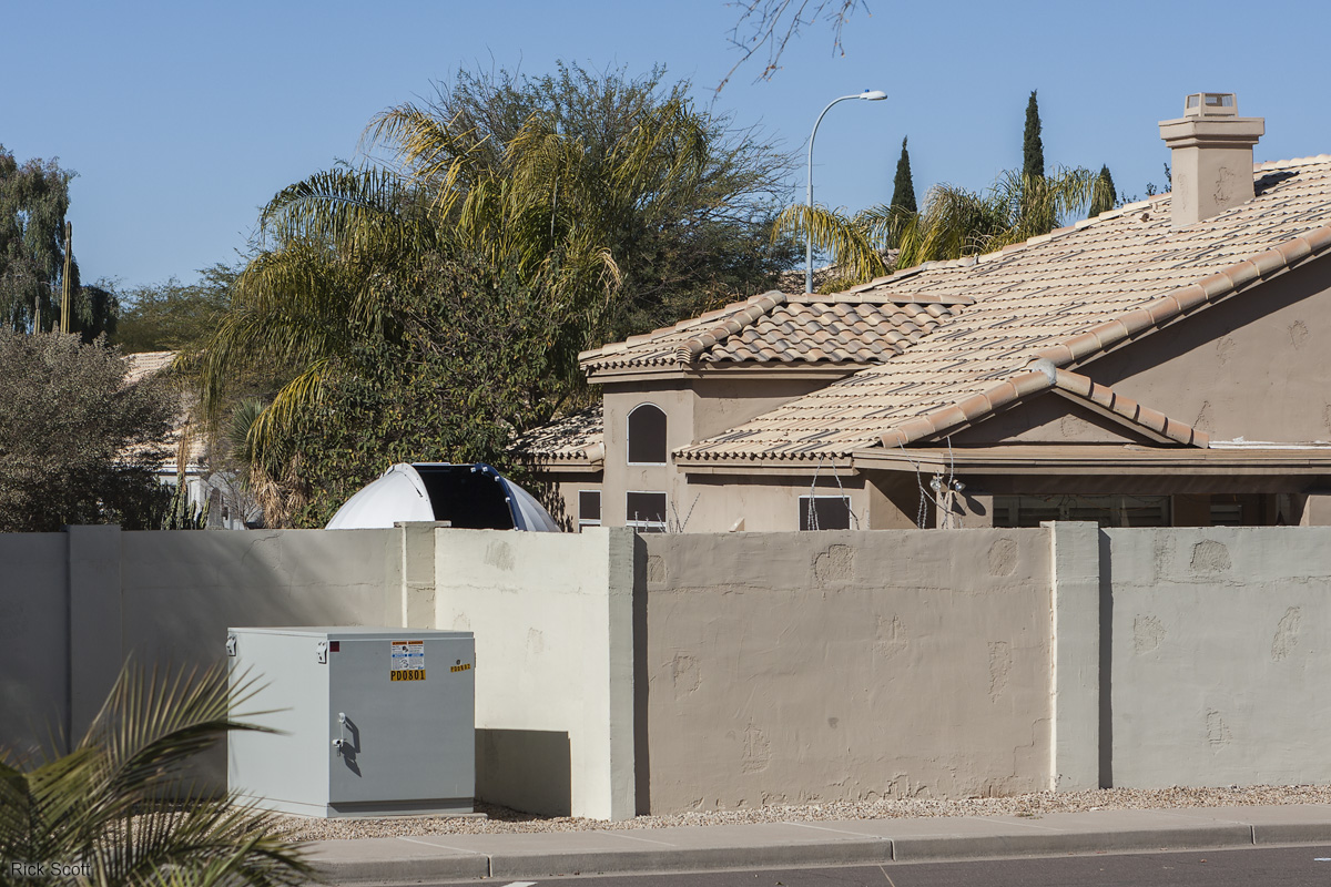
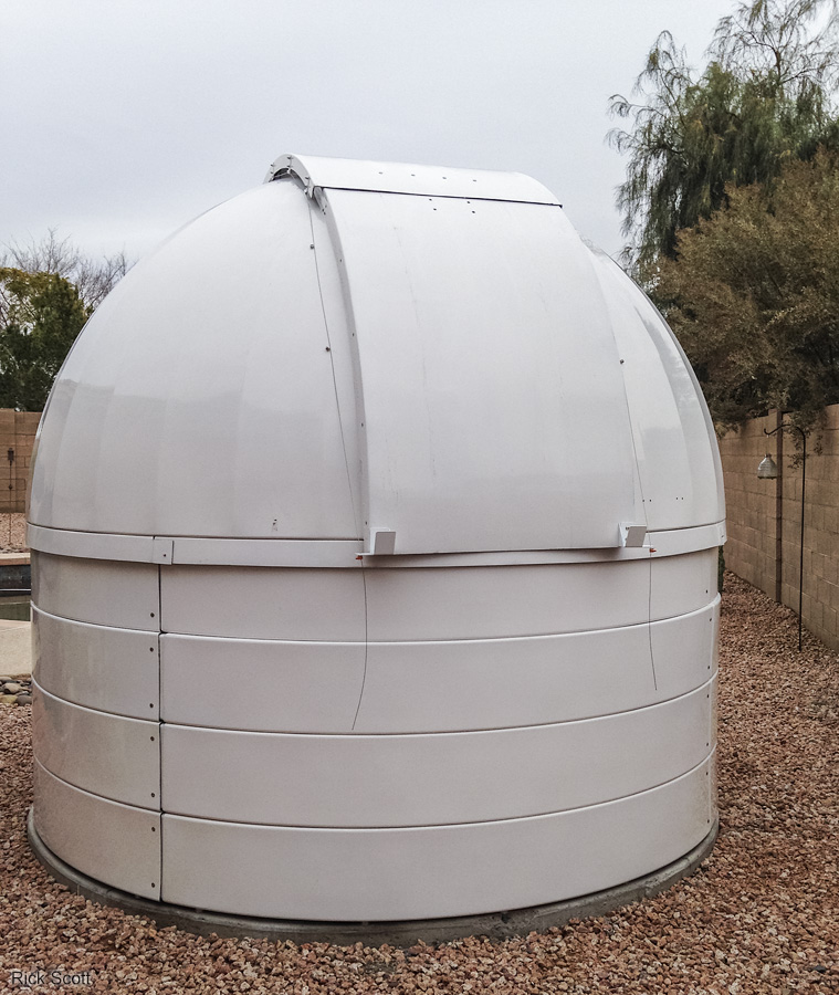
The JaZ 2 Observatory from across the street. (2/6/2016)
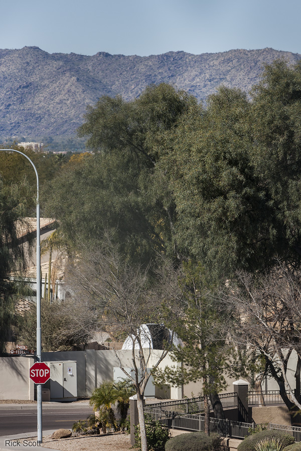
The JaZ 2 Observatory from a nearby bridge. (2/6/2016)
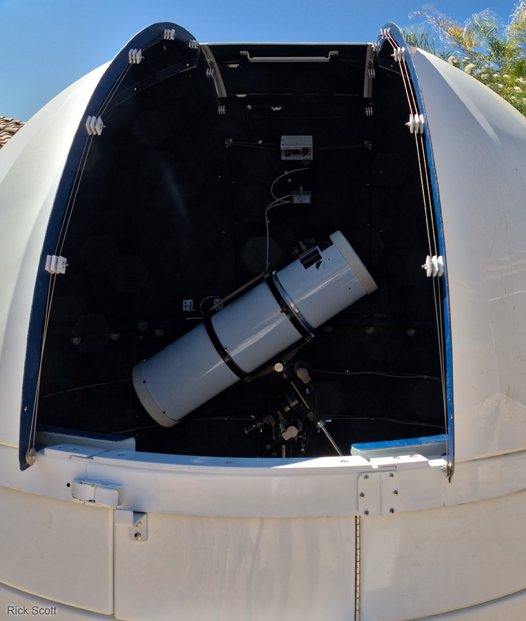
My home-made 10 inch f/4.6 Lurie-Houghton telescope through the dome slot. (3/26/2016)
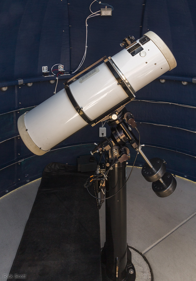
My home-made 10 inch f/4.6 Lurie-Houghton telescope in the observatory before the carpeting was put in. (3/26/2016)
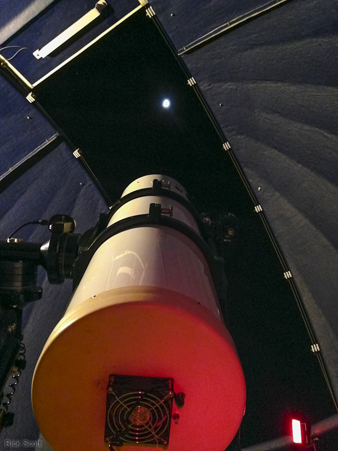
My home-made 10 inch f/4.6 Lurie-Houghton telescope aimed at the moon. The bright star Aldebaran is to the left and slight up from the moon. (2/4/2017)
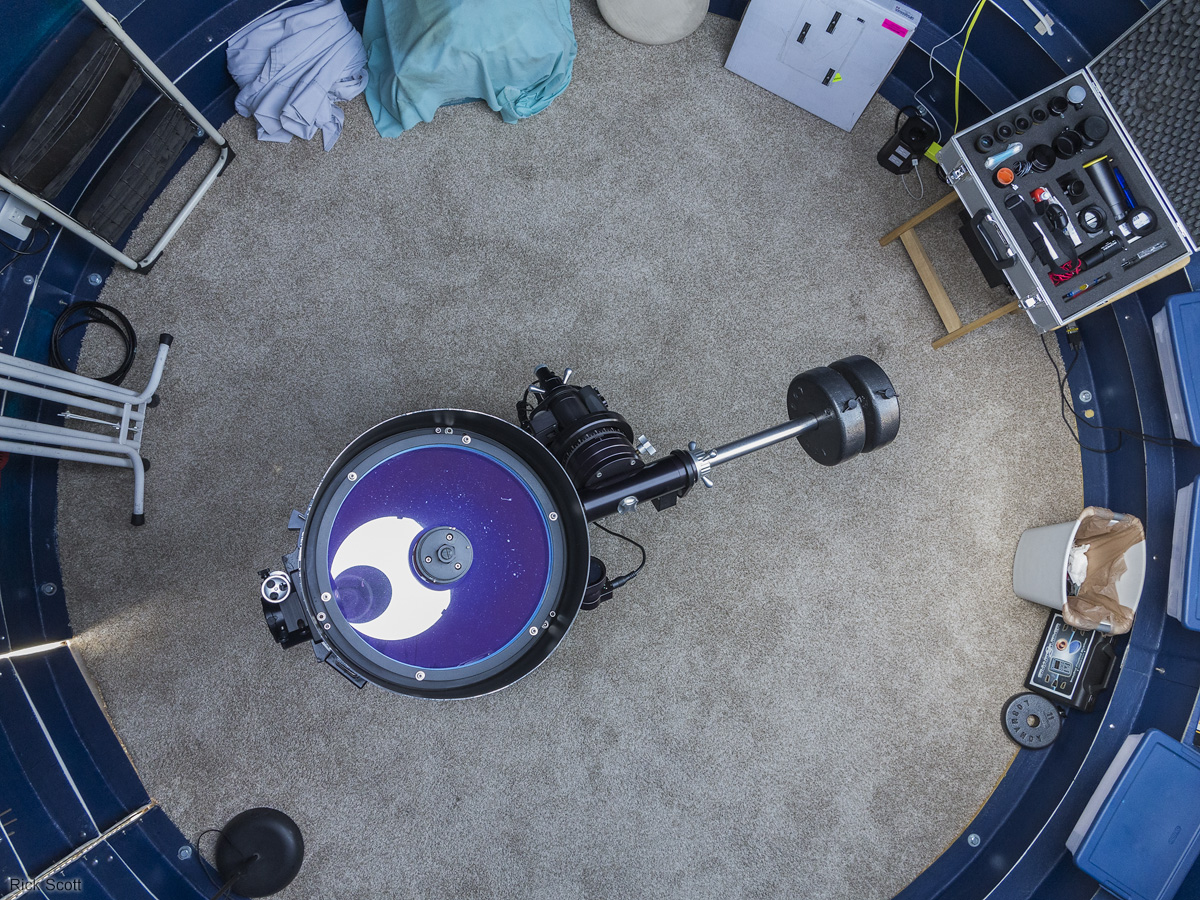
Birds-eye view looking into the observatory. (3/16/2018)